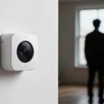
You probably don’t know that most nuisance gas alarms are caused by non-hazardous vapors or sensor drift rather than real leaks. You should expect humidity swings, transient solvent vapors, and aging sensors to trigger alerts. You’ll want a methodical check of environment, placement, and calibration to separate true events from false positives. Keep going — the next steps show how to pinpoint the root cause and stop repeat alarms.
Quick Triage: Stop False Gas Alarms Now

When a gas alarm keeps sounding, you need to act quickly and methodically to distinguish a true leak from a false positive; start by isolating variables—shutdown nonessential gas appliances, ventilate the area, and note whether the alarm persists.
You’ll proceed with a stepwise checklist: confirm detector placement and power, log recent maintenance, and note environmental changes that could cause false alarm triggers.
Use a calibrated portable monitor where available to cross-check readings; compare sensor output to expected baselines for your building.
If portable readings remain low while the fixed unit alarms, suspect sensor contamination, end-of-life drift, or electronic fault in the fixed unit.
Review manufacturer guidance on gas detection technologies to verify sensor type and known vulnerabilities.
If uncertainty remains, evacuate until a qualified technician conducts targeted diagnostics, including sensor replacement or recalibration.
Document each action and reading to support corrective measures and reduce recurrence.
Humidity, Temperature, and Transient Vapors
Although humidity, temperature, and transient vapors each affect sensor response differently, you’ll need to treat them as interacting variables during triage because their combined effects often mimic true gas alarms.
Start by documenting environmental conditions: sudden temperature fluctuations can change sensor sensitivity and response time, while humidity impact alters electrochemical and metal-oxide behavior through condensation or desiccation.
Document environmental conditions—temperature swings and humidity shifts can alter sensor sensitivity and behavior through condensation or drying.
Identify vapor sources—cleaning agents, fuel spills, vehicle exhaust—and map their transient profiles against alarm timestamps.
Use controlled tests: expose a reference sensor to isolated humidity and temperature changes to quantify sensor limitations, then introduce representative vapors to observe cross-sensitivities.
Correlate alarms with HVAC cycles, door openings, and weather patterns to separate transient ambient events from persistent leaks.
Prioritize ventilation and temporary sensor relocation to reduce false positives.
Your methodical record of conditions, actions, and outcomes improves root-cause identification and strengthens corrective guidance for maintaining reliable air quality monitoring.
Sensor Drift, Aging, and Calibration Errors
Because sensors change predictably and unpredictably over time, you’ll need a structured approach to separate true concentration changes from instrument degradation. You’ll monitor sensor performance trends, implement scheduled calibrations, and record baseline shifts so detection accuracy stays reliable. Treat drift and aging as measurable variables: quantify offset, sensitivity loss, and noise increase. Use statistical thresholds to trigger maintenance before alarms become unreliable.
| What you see | What it means |
|---|---|
| Gradual baseline rise | Sensitivity loss; aging |
| Increased noise | Electronic degradation |
| Sudden offset | Calibration error or impact |
| Reproducible change | Replace or recalibrate |
Apply documented calibration procedures, use reference gases with known concentrations, and log pre- and post-calibration results. Correlate field readings with controlled checks to separate environmental effects from sensor decline. You’ll set alarm hysteresis and auto-recalibration limits based on quantified performance metrics to protect detection accuracy without creating false alerts.
Cross‑Sensitivity to Non‑Target Gases and Vapors
You’ll need to assess how common solvents affect sensor readings, since many catalytic and electrochemical sensors react to alcohols, ketones, and other volatile solvents and can produce false positives.
You should also evaluate humidity interference, because moisture alters sensor baseline and sensitivity and can mimic or mask target gas signals.
Systematic testing under controlled solvent and humidity conditions will reveal cross‑sensitivity patterns you can correct for in calibration and alarm logic.
Sensor Reactivity With Solvents
When solvents are present in an environment, gas sensors can respond to them in ways that mimic true target-gas alarms, because many sensing technologies lack perfect selectivity and register chemical interactions rather than specific compounds.
You must evaluate sensor types (electrochemical, catalytic bead, metal-oxide, PID) for their known solvent interactions: adsorption, membrane permeation, catalytic poisoning, or photoionization cross-response.
Diagnose false alarms by comparing expected analyte behavior with sensor output across concentration, temperature, and exposure duration.
Implement controlled solvent exposure tests and use reference instruments to quantify cross-sensitivity coefficients.
Where cross-reactivity is significant, apply mitigation: filtration, selective membranes, calibration corrections, or alternate sensor modality.
Document observed solvent classes and update alarm logic to reduce nuisance trips while preserving true-gas detection.
Interference From Humidity
Although humidity is often treated as a simple environmental variable, it can directly and indirectly alter gas-sensor responses by changing surface adsorption, ionic conductivity, optical absorption, and membrane transport, producing cross‑sensitivity to non‑target gases and vapors.
You’ll observe humidity effects when a sensor’s baseline shifts, response amplitude changes, or recovery kinetics slow after moisture pulses.
Moisture interference can mimic target-gas signatures via competitive adsorption, water-layer formation that modifies catalytic sites, or altered diffusion through polymeric membranes.
To diagnose, you should perform controlled humidity sweeps, compare responses with dry calibrations, and use reference sensors or humidity compensation algorithms.
Mitigation options include hydrophobic coatings, temperature-controlled sampling, and sensor fusion; choose based on required sensitivity, response time, and environmental variability.
Sensor Placement, Airflow, and Mounting Issues

Because sensor readings depend on local concentrations and airflow patterns, placing detectors without considering ventilation and mounting height often causes false alarms or missed detections.
You must assess sensor orientation relative to expected gas sources and dominant air currents; mounting a detector perpendicular to a laminar flow or in a dead-air corner will give misleading local concentrations.
Consider environmental factors such as temperature gradients, drafts from HVAC returns, and proximity to doors or exhausts that create transient spikes.
Mount sensors at heights appropriate for the gas’s buoyancy, and avoid positioning near obstructions that produce eddies.
Use methodical placement: map airflow, run tracer tests, and validate with temporary monitors before final installation.
Secure mounting prevents vibration-induced variability and preserves calibration alignment; loose brackets change orientation and sample exposure.
Finally, document placement rationales and periodic inspections so you can distinguish true gas events from placement- or airflow-induced anomalies.
Electrical Noise, Grounding, and Interference
If you don’t control electrical noise and grounding, sensor signals can be distorted, causing false alarms or missed events; you’ll need a systematic approach to identify, mitigate, and document interference pathways.
Start by characterizing the problem: measure waveform noise, log alarm timestamps, and correlate with nearby electrical activity. Test for ground loops and verify electrical grounding continuity with low-impedance measurements.
Separate power and signal cabling, route cables orthogonally to noisy conductors, and use twisted-pair or shielded cables where appropriate.
Implement filtering at both hardware (RC filters, common-mode chokes) and software (digital filtering, debounce logic) layers, but validate that filters don’t obscure genuine gas transients.
Use proper cable termination and shield grounding practices to minimize signal interference without creating new ground paths. Record all changes, test under representative operational loads, and repeat tests after any electrical or layout modification.
A methodical, measured process reduces false positives while preserving detection sensitivity.
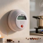
Sensor Contamination and Protective‑Cap Mistakes
When sensors are exposed to contaminants or left capped incorrectly, their responses can drift or lock out, so you need a disciplined inspection and handling routine to prevent avoidable false alarms. You’ll inspect sensor types for particulate buildup, corrosion, or solvent residues that change sensitivity. You’ll follow handling steps: remove protective caps only in clean areas, avoid touching sensing surfaces, and document cap removal times. You’ll track contamination sources — dust, oils, cleaning agents — and correlate them with alarm trends. Calibration frequency should increase if contamination risk is high. Replace or clean sensors per manufacturer procedures; do not improvise. Use checklists to verify caps are reinstalled when work is done. The table below helps prioritize actions and responsibilities.
| Item | Action | Frequency |
|---|---|---|
| Visual inspection | Check sensing surface, caps | Daily |
| Contamination log | Record sources, incidents | Per event |
| Cleaning/replacement | Follow OEM procedure | Per risk level |
| Cap control | Marked storage, check | Each maintenance |
Detector Firmware, Telemetry, and Configuration Errors
Contamination and mishandled caps aren’t the only causes of false alarms — device software, telemetry links, and configuration errors often produce misleading readings that mimic sensor faults.
You need to treat detector updates cautiously: automatic patches can change calibration parameters or data interpretation logic without visible alerts. Firmware bugs may corrupt sample timing, apply incorrect compensation factors, or fail to handle edge-case inputs, producing spurious concentrations.
Telemetry failures—packet loss, buffering, timestamp drift—can misalign events and make transient spikes look persistent. Configuration errors, like incorrect sensor type selection, alarm thresholds, or sampling intervals, will generate predictable yet false exceedances.
You should maintain strict version control, document changes, and validate updates in a controlled environment before deployment. Use checksums and signed firmware to prevent unauthorized code.
Monitor telemetry health metrics separately from gas readings so communication issues aren’t mistaken for sensor failures. Implement conservative defaults and rollback procedures to minimize operational risk when software or configuration is suspect.
Diagnose the Root Cause : Stepwise Testing and Logs
Because false alarms can stem from firmware, telemetry, or configuration issues, you should follow a disciplined, stepwise diagnostic process that isolates variables and records evidence at each stage.
Start by documenting the event timeline: sensor readings, timestamps, firmware versions, telemetry packets, and configuration snapshots. Reproduce the event in a controlled environment, changing one parameter at a time—power source, communication channel, firmware build, calibration offset—so you can attribute any change in behavior to a single factor.
Document the event timeline—readings, timestamps, firmware, telemetry and configs—then reproduce it, changing one parameter at a time.
Collect and correlate logs from the detector, gateway, and historian; look for anomalies, packet loss, CRC errors, or unexpected resets. Use statistical filters to separate transient spikes from persistent deviations.
When a test reproduces the alarm, perform root cause analysis: trace the chain from symptom to failing component or setting. Verify fixes by repeating the same stepwise tests and confirming log signatures return to normal.
Record all findings for traceability and future troubleshooting.
Prevention and Maintenance Checklist to Reduce False Alarms
You should implement a documented sensor cleaning schedule to remove particulate buildup that can trigger false readings.
You’ll also need routine calibration and functional testing to verify sensor accuracy and response times.
Finally, control environmental factors—ventilation, temperature, and humidity—to keep readings within expected operating conditions.
Sensor Cleaning Schedule
Although sensors can seem maintenance-free, establishing a strict cleaning schedule is essential to prevent deposits and residues from triggering false gas alarms. You’ll want a checklist that specifies cleaning frequency, approved methods, responsible personnel, and documentation procedures so each sensor is serviced consistently and auditably.
You should define sensor maintenance intervals based on environment, manufacturer guidance, and historical fouling rates. Assign trained staff, record serial numbers, dates, actions taken, and consumables used. Use only approved solvents, tools, and PPE to avoid sensor damage.
Incorporate visual inspection, noninvasive surface cleaning, and replacement criteria for compromised housings. Review cleaning frequency quarterly or after process changes. Audit records monthly to verify compliance and adjust intervals when data show increased false positives or contamination trends.
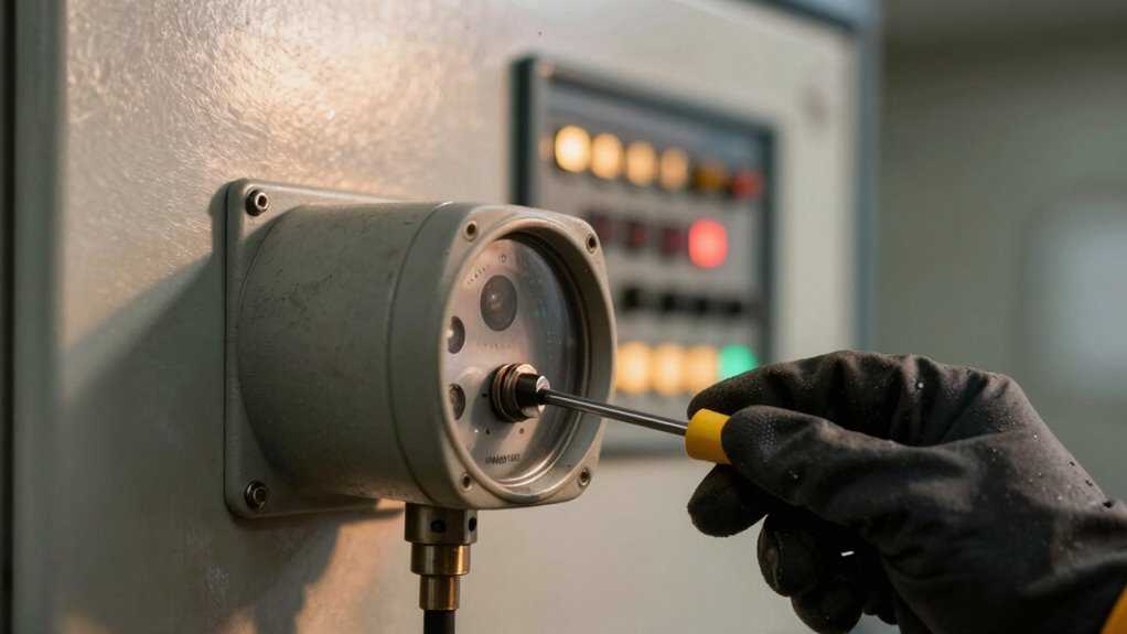
Calibration And Testing
When calibration and testing are scheduled and executed systematically, they’ll cut false alarms by ensuring sensors respond accurately to known gas concentrations and that drift or cross-sensitivities are caught early; the checklist should consequently specify calibration intervals, reference gas types and concentrations, acceptance criteria, procedural steps for span and zero adjustments, and pass/fail actions so each event is repeatable and auditable. You should define calibration frequency based on sensor type, manufacturer guidance, and operational risk, and document testing procedures that include pre-test inspection, application of certified reference gas, stabilization time, and recorded results. Use a clear log entry format to track trends and corrective actions. Below is a compact checklist table for routine use.
| Item | Action | Acceptance |
|---|---|---|
| Interval | Set per risk | Pass/Fail |
| Reference | Gas type/conc | Certificate |
| Procedure | Step sequence | Timestamp |
| Adjustment | Span/zero | Logged |
| Action | Corrective step | Verified |
Environmental Controls
Because environmental factors are a primary source of false gas alarms, your prevention and maintenance checklist should methodically control and monitor conditions that affect sensor performance—temperature, humidity, airflow, dust, chemical contaminants, and electromagnetic interference—by specifying acceptable ranges, monitoring methods, mitigation actions, and inspection frequency.
You’ll document baselines and tolerances, tie alarms to deviations, and prioritize actions that restore detection reliability quickly. Implement routine verification and corrective steps so drift doesn’t compound.
- Define acceptable ranges for each environmental factor and log continuous or periodic measurements.
- Specify inspection frequency, cleaning protocols, and filter replacement intervals to limit dust and contaminants.
- Establish responses for out-of-range conditions: ventilation adjustment, sensor relocation, or temporary shutdown.
- Record corrective actions and revalidate sensor calibration to confirm restored detection reliability.
Frequently Asked Questions
How Do False Alarms Affect Insurance or Liability Coverage?
False alarms can complicate insurance implications and heighten liability concerns: you’ll face higher premiums, denied claims if negligence’s proven, and potential litigation; document maintenance, calibration, and response protocols to defend coverage and limit exposure.
Can Pets or Pests Trigger Gas Detectors?
Yes — pets or pests can trigger gas detectors. You’ll find pet behaviors (shedding, grooming, spraying) and pest presence (rodent nests, insect aggregations) can release odors or particulates that confuse sensors, so investigate and mitigate systematically.
Do Construction or Renovation Activities Increase False Alarms?
Yes, construction or renovation activities can increase false alarms: construction dust clogs sensors and renovation fumes (solvents, paints) alter sensor readings, so you should isolate detectors, use filtration, and schedule calibrations methodically.
Are Portable Detectors as Reliable as Fixed Systems?
Yes — you can expect portable detector accuracy to approach fixed system reliability for spot checks, but you’ll need regular calibration, consistent placement, and environmental controls; fixed systems still outperform for continuous, networked monitoring and alarm management.
Can Smartphone Apps Cause Detector Communication Errors?
Absolutely — you could say your phone alone might topple a refinery: smartphone interference from apps can disrupt detector communications, so you shouldn’t assume app reliability; test interfaces, isolate networks, and log anomalies methodically.